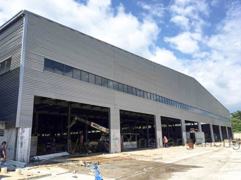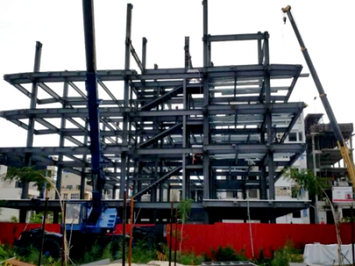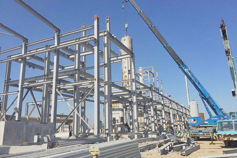
Portal frames are widely used for warehouses, factories, hangars, and logistics buildings because they provide clear internal space and repeatable fabrication. For overseas contractors involved with the construction of portal frames, production can commence only after careful consideration of geometry, loads, connection detail, bracing, foundations, site transport, and initial site erection.
A suitable steel structure factory would translate these requirements into approved shop drawings, marked-up components, connections, and a site installation program ready for start.
What Is a Steel Portal Frame and Where Is It Used?
How Rigid Frame Action Creates Clear Internal Space
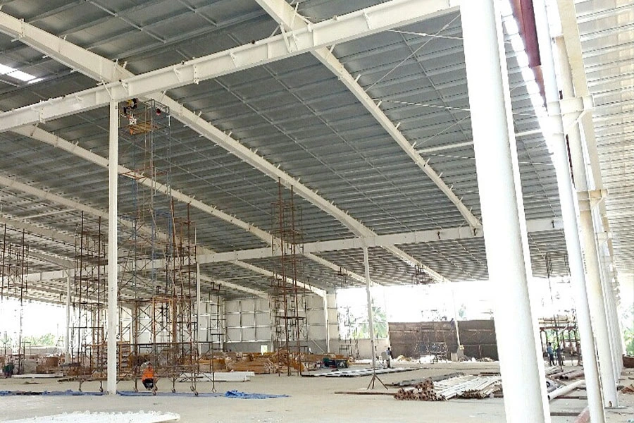
A steel portal frame is formed by columns and rafters connected through moment-resisting joints. The frame carries roof loads to the foundations and resists horizontal forces caused by wind and building use. Because the main frames span across the building width, many projects can avoid internal columns.
This arrangement suits warehouses, manufacturing plants, aircraft hangars, agricultural buildings, and commercial workshops. Clear floor space supports production lines, storage racks, vehicle movement, large doors, and later layout changes. Standardized bays also simplify fabrication and erection.
Which Portal Frame Configuration Fits the Project?
The structural arrangement should follow operational requirements rather than a standard catalogue layout.
| Frame option | Suitable applications | Main issue to verify |
| Clear-span portal frame | Warehouses and workshops | Rafter depth and deflection |
| Propped portal frame | Very wide buildings | Internal column location |
| Multi-bay portal frame | Large industrial facilities | Drainage and braced bays |
| Mono-pitch portal frame | Extensions and special roofs | Uneven reactions and drainage |
A portal frame often suits projects needing a repetitive system and unobstructed floor area. A truss may suit certain long spans or concentrated roof loads, but it introduces more members and connections. The decision should follow project-specific steel portal frame design.
What Are the Main Steel Portal Frame Components?
How to Read a Portal Frame Components Diagram
A useful portal frame components diagram should identify the columns, rafters, apex, eaves, portal frame haunch, purlins, girts, eaves struts, roof bracing, wall bracing, base plates, anchor bolts, and cladding supports. It should also show the clear span, bay spacing, eaves height, roof pitch, frame direction, and braced bays.
These labels help purchasing and erection teams distinguish primary from secondary steelwork and confirm cranes, mezzanines, openings, and service routes.
Columns, Rafters, and the Portal Frame Haunch
Columns transfer vertical and horizontal forces to the foundations. Rafters carry roof loads between the eaves and apex. Their section sizes depend on span, bay spacing, load combinations, and deflection limits.
The portal frame haunch is normally positioned near the eaves, where bending moments can be high. Increasing the effective section depth in this area improves stiffness and supports the eaves moment connection. Haunch length, plate thickness, welds, stiffeners, and bolt arrangement must follow the structural calculations and fabrication drawings.
A haunch should not be treated as a standard accessory that can be copied between projects. Changes in roof slope, frame spacing, column size, crane loads, or environmental loads may require a different haunch configuration.
Purlins, Girts, Base Plates, and Cladding Supports
Purlins support roof panels and transfer loads to the rafters. Girts or side rails support wall panels and transfer wind pressure to the columns. Eaves struts link the roof and wall restraint systems, while other secondary members provide restraint where required.
Base plates distribute column forces into the foundation. Anchor bolts position the columns and transfer forces according to the approved detail. Their setting-out dimensions must be checked before concrete placement.
Roof and wall systems also need to be coordinated with the structural frame. Purlin spacing, panel direction, insulation requirements, skylights, gutters, and wall openings can all affect the secondary steel layout. These details should be settled before materials are fabricated.
How Do Bracing and Connections Keep a Portal Frame Stable?
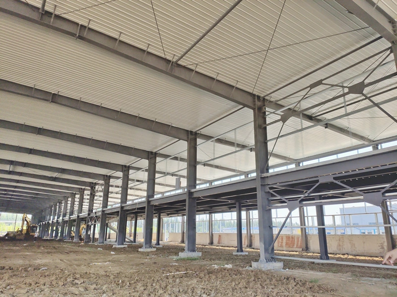
How a Portal Frame Bracing System Transfers Longitudinal Loads
The transverse frames resist forces across the building width, but longitudinal stability requires a separate load path. A portal frame bracing system commonly uses roof bracing, wall bracing, eaves struts, and member restraints to carry forces along the building to selected foundations.
Braced bays must be coordinated with loading doors, windows, conveyors, and equipment. Removing a diagonal brace on site without redesign can interrupt the load path. Frames may also need temporary supports until permanent bracing, purlins, and wall members are installed.
For buildings with several large door openings, the bracing layout should be reviewed early. Moving a braced bay after fabrication may require changes to cleats, wall members, foundations, and erection drawings.
Portal Frame Connection Details at the Eaves, Apex, and Bases
Portal frame connection details must develop the forces assumed in the design. The main connection groups are:
- Eaves connections between columns, rafters, and haunches.
- Apex connections joining the roof rafters.
- Base plate and anchor bolt connections.
- Bracing cleats and secondary member joints.
- Transport splices for members that exceed shipping limits.
Before fabrication, contractors should confirm plate thicknesses, bolt grades, holes, welds, stiffeners, splice positions, erection orientation, and component marks.
Connection design should also consider practical site assembly. Bolts need sufficient access for tightening, splice locations should support safe lifting, and component orientation should be clear from the drawings. A structurally adequate detail can still create installation delays when site access has not been considered.
Which Design Inputs Should Contractors Confirm Before Fabrication?
Span, Bay Spacing, Height, and Operational Loads
The design team needs the clear span, bay spacing, eaves height, roof pitch, door dimensions, building use, and possible future expansion. The loading brief should cover wind, snow, seismic conditions, suspended services, solar panels, cranes, mezzanines, and roof-mounted equipment.
For custom metal warehouse designs, rack positions and vehicle routes can affect clearances and openings. A practical review sequence is:
- Confirm the architectural grid and clear dimensions.
- Confirm design codes and environmental loads.
- Coordinate cranes, openings, services, and mezzanines.
- Approve foundation reactions and anchor bolt plans.
- Review connections and transport splices before releasing shop drawings.
Overhead cranes require particular attention. Crane capacity, runway level, operating class, bracket position, and horizontal forces can affect the columns, bracing system, and foundations. These requirements should not be added after the mainframe has already been designed.
Foundations, Transport, and Erection Tolerances
Portal frame construction must be coordinated as a complete system. Foundation levels, bolt projections, grout gaps, slab edges, drainage, and wall panel lines all affect installation.
Long rafters may need factory splices to meet road, container, or port restrictions. Splice positions should support safe lifting and assembly. Documents should also define checks for column plumb, frame spacing, bolt tightening, temporary bracing, and purlin alignment.
Packaging should follow the erection sequence where practical. Columns, rafters, bracing, bolts, and secondary members need clear identification so that the site team can locate each item without opening every package. This is especially important for overseas projects with limited storage space or phased deliveries.
How Should Contractors Evaluate a Steel Structure Factory?
Engineering Coordination, Fabrication, and Installation Support
For overseas projects, supplier evaluation should focus on coordination capability, not production volume alone. XINGUANGZHENG integrates research and development, design, production, installation, and after-sales service. The company reports six production plants, seven steel structure production lines, two purlin lines, and more than 100 senior technical personnel supporting project design and technical work.
Our team connects the design brief with shop drawings, production scheduling, packing, delivery, and installation assistance. Contractors should verify code capability, drawing review, member identification, hole and weld inspection, and installation support.
A supplier review should answer several practical questions:
- Can the factory work with the required design standard?
- Are structural and fabrication drawings reviewed before cutting begins?
- Are columns, rafters, bracing, and secondary members clearly marked?
- Are bolt holes, connection plates, welds, and dimensions inspected?
- Can technical or installation guidance be arranged when required?
Clear responsibilities at each stage reduce the risk of design changes being missed during production.
Project Examples With Different Portal Frame Requirements
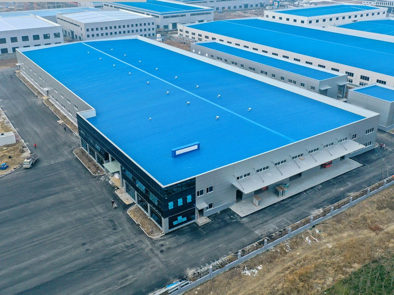
XINGUANGZHENG has supplied building projects in more than 100 countries, including plants, warehouses, cold storage facilities, hangars, and agricultural buildings.
Case 1: An auto parts factory used a portal steel frame for a 12,000-square-meter building with a maximum span of 40 meters. The project illustrates the need to coordinate clear-span requirements, production space, member design, and bracing locations.
Case 2: A warehouse in Thailand covered 15,372 square meters and used an 8-meter column spacing. It also included a three-floor office area and four 2-ton overhead cranes, showing how equipment and internal functions affect the frame grid and loads.
These cases show why structural steel portal frames should reflect building use, equipment, openings, enclosure, transport, and site conditions. Contractors can review our projects or contact our team about a customized steel structure solution.
FAQ
Q: What should a portal frame components diagram include?
A: It should identify the primary and secondary members, the apex and eaves, haunches, braced bays, base connections, span, bay spacing, eaves height, roof pitch, major openings, and frame direction.
Q: What is the purpose of a portal frame haunch?
A: The haunch increases stiffness near the eaves and helps transfer bending forces through the column-to-rafter connection. Its dimensions and connection arrangement must be determined by the structural design.
Q: How does a portal frame bracing system improve stability?
A: It transfers longitudinal wind and other horizontal forces through the roof and walls to the foundations. It also restrains members and helps maintain stability during erection when installed in the specified sequence.
Q: Which portal frame connection details should be checked before production?
A: Contractors should check eaves and apex joints, base plates, anchor bolts, transport splices, bracing cleats, bolt grades, plate thicknesses, weld requirements, hole positions, stiffeners, component marks, and erection orientation.
Engineering Inputs to Confirm for a Steel Structure Project
Concept selection should be based on the building use, required clear span, column grid, eave height, equipment and crane loads, service openings, envelope system and local design criteria. Site wind, snow, seismic and corrosion conditions must be confirmed before structural sizing. The quotation should also distinguish engineering, fabrication, delivery, erection guidance and work assigned to the local contractor.
See our industrial steel structure applications, review steel structure design and fabrication support, explore project examples, or submit your project inputs for an initial review.